The importance of thermal fluids simulation.
Conceptually, a diesel engine is just a simple heat pump that combines air and fuel in the right proportions at the right time. The resulting hot, high-pressure combustion gasses then drive the pistons that turn the crankshaft and power whatever it’s connected to.
The concept isn’t complicated at all. Making it work in the real world, however, is an entirely different story.
It takes thousands of hours of skilled engineering to design a working engine and thousands more to prototype, test and put it into production. Get any aspect of the design wrong, and it can literally be ‘back to the drawing board’ and start over.
Seeing the unseeable
A major part of Tim Ward’s job is to help make sure that doesn’t happen. He is the manager of the Perkins thermal fluids simulation team and an expert in computational fluid dynamics. In simple terms, that means the team uses computer models and simulations to understand how air, fuel, oil, coolant and exhaust gasses flow and interact inside an engine.
“Using advanced computer models we can ‘see’ how the various fluids flow inside an engine,” Tim explained. “We can explore design options and understand their impact long before any physical components are produced. Working closely with the design teams we can optimise the fluid flows to help assure that the physical prototypes will deliver the expected performance when tested.
“Basically,” he continued, “our job is to help make sure we get everything right the first time by looking at things inside the engine that nobody can ever see in reality.”
Small change, big impact
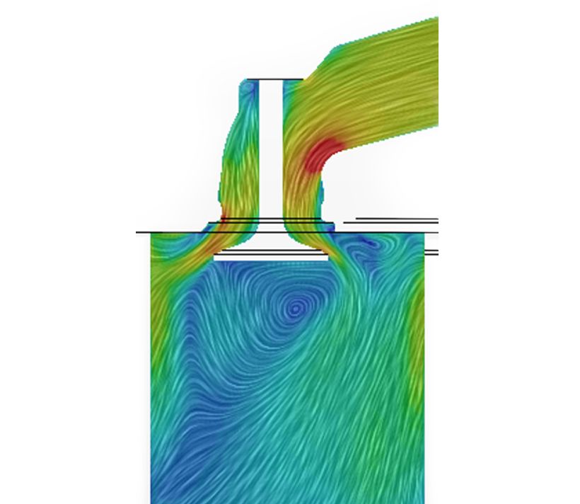
Even small changes can have large impacts. Changing the shape of the piston or the exact angle at which fuel is injected, for example, can substantially reduce or increase both oil ‘sooting’ and emissions.
Oil ‘sooting’ occurs when unburned ‘soot’ in the combustion gasses comes into contact with the lubricating oil on the cylinder wall. The oil is pulled down by the piston and eventually deposited in the sump. The accumulating ‘soot’ degrades the oil’s lubrication properties and shortens its service life.
It’s important to control oil ‘sooting’ because extended oil change intervals are one of the features of Perkins newest engines, particularly those meeting EU Stage V emission standards. By simulating the combustion process, Tim’s team can help engineers optimise both piston geometry and injector orientation to minimise ‘soot’ formation, and keep any ‘soot’ that is produced away from the cylinder wall as much as possible.
“Because we can ‘see’ the combustion process in the simulation, we can tune it and examine various options very quickly,” Tim said. “That lets us understand their impact on performance, emissions and oil “sooting’ when gasses are burning close to where the oil is.”
Another place where small changes can have large impacts is in the Exhaust Gas Recirculation (EGR) system that is part of the emission controls. EGR introduces measured quantities of exhaust gas into the intake air stream to help reduce NOx emissions.
“It’s important that the exhaust gas mixes properly with the incoming air so it’s distributed equally between all the cylinders,” Tim said. “If it isn’t, it impacts the emissions coming out of the engine.
“You can’t see the mixing on an operating engine, but you can simulate it and make small changes to improve it.”
Air traps and add-ons
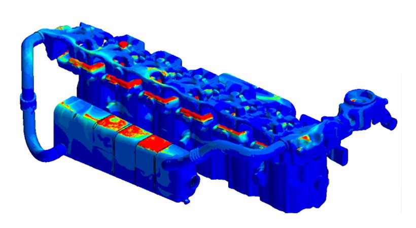
Air and fuel aren’t the only fluids Tim’s team studies, coolants and coolant flows are also modelled and simulated. Beside assessing the heat transfer performance of a proposed cooling system, the team also looks for places where air might be trapped in the coolant passages when the system is filled.
At worst, a serious air pocket ‘trap’ might necessitate a redesign of the coolant passage, a new prototype and new testing. That could delay completion of the engine project and add significant expense.
“An equally important consideration,” Tim added, “is that a customer might have to top up their coolant after an initial fill because of the trapped air. We go to great lengths to maintain the Perkins reputation for quality and ensure that such things don’t happen.”
Cooling system models can also help customers optimise the performance of ‘bolt on’ accessories like cabin air conditioning and heating systems. Cooling system simulation models can ‘connect up’ such customer add-ons to evaluate their impact on the system.
The results are shared with customers along with recommendations to make the application more successful. The team uses the same process to evaluate hydraulic and other customer ‘bolt on’ systems.
“If we don’t get it right,” Tim noted, “it can impact engine performance. It’s a lot more expensive and time consuming to do it on an actual engine where we would have to fabricate components and then run multiple physical tests. This way, we can be reasonably sure to get it right the first time.”
Whole systems too
Simulation and modelling isn’t limited to individual engine sub-systems. Tim’s team has the resources to evaluate multiple systems and their interactions simultaneously.
For example, to evaluate the lubrication system, a simulation must integrate models for the oil pump, the turbocharger and various other lubrication dependent engine sub-systems. It must also take into account the effects of both high and low temperatures on the oil itself.
Tim’s team is able to simulate how long it takes for oil to get from the sump to the turbocharger at various temperatures and oil viscosities. They also can see what the pressures are at any point, once again helping to get it right the first time to minimise development time and cost.
The results of those, and other, simulations are combined with hot and cold chamber test results and nearly a century of real-world experience to produce the Perkins fluid guidelines customers around the world depend on.
Compact aftertreatment, big performance
Perkins newest engines are engineered to meet Stage V emission standards while providing increased power density from a physically smaller package. That means both the engine and the aftertreatment components are engineered to be as compact as possible while still delivering leading edge performance.
Tim’s team had a hand in meeting those goals. They studied pressure drops through the system, identified restrictions and determined their impact on engine performance before anything was built and tested.
“Engines are designed to meet a certain requirement,” Tim said, “and if the aftertreatment system does not meet the need the whole system won’t work together.”
Perkins engines are used in some of the hottest and coldest and highest and lowest places in the world. They have supplied efficient, reliable power for nearly a century and meet lower-carbon and emission standards.
The simulation and modelling tools used by Tim’s team have played no small part in that success. Getting it right by watching things they can’t see is a proven way to keep making things better.
Tim recently caught up with industry journalist Peter Haddock for his Discovering the Power of Perkins video series. Check out the video below.
-
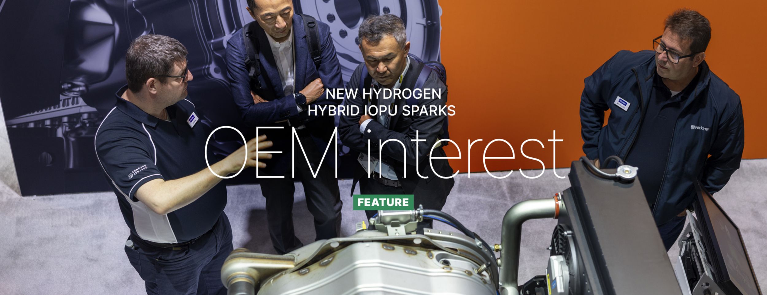
New hydrogen hybrid IOPU sparks OEM interest
CONEXPO-CON/AGG in March 2026 was the first showing of Perkins’ advanced fuel-configurable hybridised industrial open power unit (IOPU).
Read more -
The power of light towers
Behind the scenes at many global data centre development sites, stand a fleet of humble light towers, making 24/7 progress possible.
Read more -
Solving agricultural power needs
Facing an evolving energy landscape, Perkins is again applying its innovation to provide fresh power concepts.
Read more -
The future of off-highway power is about integration
We talk to Perkins vice president Richard Hemmings about our customer first approach.
Read more -
Raw agricultural power in Brazil
Powernews ag correspondent Adrian Bell gives us a snapshot of the impressive agricultural industry he observed – and its back story.
Read more -
Powering ahead in marine
We investigate why customers return to Perkins time and again.
Read more -
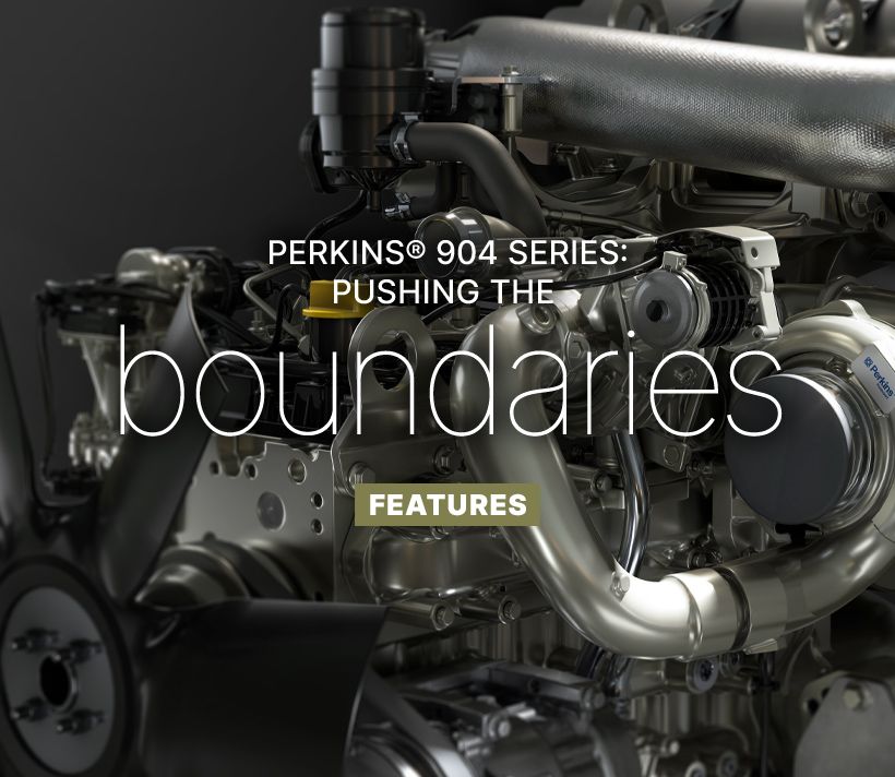
Perkins® 904 Series: pushing the boundaries
The new model will deliver up to 129 kW (173 hp) and 740 Nm (546 lb ft) at 1500 rpm, from a compact 3.6 litre engine.
Read more -
High‑reliability power systems: The silent guardians ensuring data centre uptime
Ensuring uninterrupted performance is non-negotiable, at the heart of that reliability sits the diesel-powered generator.
Read more -
Built to make a difference: The new 5000 Series is driving progress around the world
Providing dependable power output up to 2500 kVA for standby and 2250 kVA for prime applications.
Read more -
Powering forward: Richard Hemmings on innovation, reliability and what comes next
Powernews caught up with new VP Richard Hemmings to learn more about his new role.
Read more


Also in this issue
-
New marine engines exhibited
A new range of auxiliary marine engines were shown at METS.
Read more -
California: the state that feeds America
Adrian Bell dives into the history of Californian agriculture.
Read more -
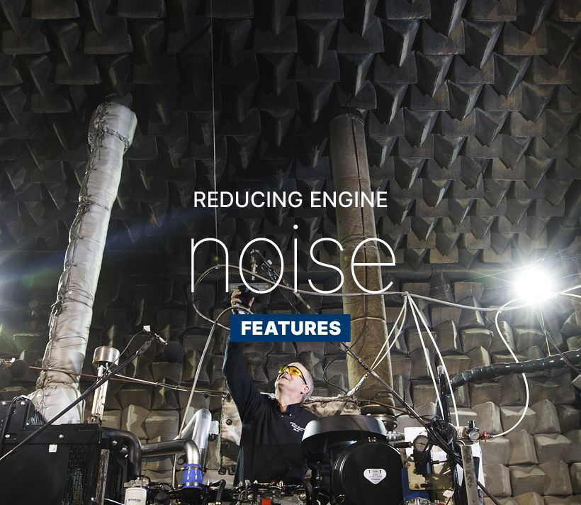
Reducing engine noise
How ‘noise chambers’ help Perkins build quieter engines.
Read more -
The Agrievolution Alliance
The global voice for agricultural equipment manufacturers.
Read more -
Interview with Ann Brown
Meet our Vice President of facility operations.
Read more