Providing an insight for Powernews readers is Andy Miller, Perkins’ product support manager, who has more than 15 years’ experience in the diesel engine industry.
The basic principle of fuel injection is that the right amount of fuel must be injected at the right time to satisfy engine horsepower demands. Since fuel requires time to burn, the right amount of fuel must be injected at the appropriate point in the compression stroke, so that it burns completely.
Over the years a number of different systems have been developed to implement and control the fuel injection process. These can be broadly categorised into mechanical and electronic approaches, although, as we will see, a number of variations exist. Nevertheless, the basic principles of diesel fuel systems are consistent regardless of the technology used to implement them.
In diesel engines, fuel is injected during the compression stroke before the piston reaches top dead centre (TDC). Only the air is compressed on the compression stroke which causes it to become hot enough to ignite the fuel.
In a mechanical system, the fuel charge is accurately metered and pressurised by the fuel injection pump and passed to the high-pressure injectors via pipes before being sprayed into the combustion chamber, where it ignites. The resulting combustion gasses then drive the piston down to produce the power stroke.
The principle is the same in electronic systems, but the components are different. Since mechanical systems were the first to be developed and used it’s reasonable to start by describing them.
A mechanical fuel system contains a low-pressure circuit and a high-pressure circuit. Fuel flows through the components in the fuel system as follows: The transfer or lift pump draws fuel from the fuel tank through the inlet port of the primary fuel filter which may contain a water separator, to remove water from the fuel.
After flowing through the primary filter and reaching the transfer pump, the fuel is pressurised before flowing to the secondary fuel filter. The fuel flows under low-pressure into the high-pressure fuel injection pump.
The transfer pump typically is a simple diaphragm type actuated by a cam lobe acting on a lever that depresses and releases the spring-loaded diaphragm to move the fuel. Electric transfer pumps also are used on some engines.
In any case, the only function of the transfer pump is to deliver an adequate flow of fuel to the injection pump.
The injection pump is often a rotary plunger-type unit with an individual piston for each cylinder of the engine. Or, it may be a single chamber pump that meters fuel to each cylinder using a sleeve or scroll system. In either case, the pump sends a small amount of fuel through the high-pressure fuel line to each injector in the appropriate sequence.
When the fuel pressure exceeds the injector nozzle’s pre-set pressure limitation it opens, and fuel is injected into the combustion chamber. Any excess fuel is sent out through a return line back to the fuel tank.
Because all of these functions are performed in what is essentially a closed loop that generates positive feedback, a diesel engine requires a governor to regulate fuel delivery and keep the engine from over speeding. Diesel engines are not self-speed-limiting because the air (oxygen) entering the engine is always the maximum amount. Therefore, the engine speed is limited solely by the amount of fuel injected into the engine cylinders. The engine should always have sufficient oxygen to burn and the engine will attempt to accelerate to meet the new fuel injection rate.
In a mechanical system the governor operates on the principle of balancing flyweight force against spring force. Normally, an engine is operating under some sort of load and the governor determines what engine rpm is correct for the applied load and operator input. The governor provides the engine with the feedback mechanism required to change speed as needed and to maintain the desired speed.
Obviously, there is a significant amount of technology involved in manufacturing and integrating the elements of a mechanical fuel system into a diesel engine. But, regardless of the details the basic principles are essentially the same. Those principles also apply to the electronic systems increasingly found on modern diesels that have been developed in response to increasingly stringent global emission standards.
Mechanical Electronic Unit Injectors (MEUI) and Hydraulic Electronic Unit Injectors (HEUI) were among the first technologies to successfully replace mechanical components on the high-pressure side of the fuel system. They replace the injection pump, fuel lines, and nozzles used in mechanical engines with an electronically triggered unit injector in each cylinder.
Low pressure fuel is delivered to each injector through a gallery in the cylinder head, eliminating individual fuel lines. The fuel is then pressurised inside each injector with a mechanically or hydraulically powered plunger and released into the cylinder by a solenoid responding to an electronic signal from the Engine Control Module (ECM).
The ECM, which monitors multiple engine functions, eliminates the need for a mechanical governor. The resulting fuel system is both simpler and simultaneously more precise. As was the case with mechanical fuel systems, a number of advancements have been made since MEUI and HEUI were introduced.
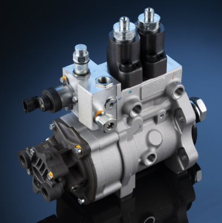
The most recent step in the evolution of electronic fuel systems is common rail technology. Instead of pressurising fuel in the injector, a dedicated fuel pump is used to generate high fuel pressure and deliver it to a fuel manifold, or rail. From there, the high-pressure fuel flows through individual steel fuel pipes to electronically controlled injectors.
Since the fuel is supplied at injection pressure the injectors themselves can be much simpler and more responsive. This allows fuel to be injected in precise quantities at more than one point during the combustion cycle to produce more complete and, therefore, efficient, combustion. This process is controlled by a sophisticated ECM that monitors and responds to multiple engine, machine and operator inputs.
It’s important to note that in common rail fuel systems the fuel injection pump supplies fuel to the manifold and injectors at pressures up to 200 MPa (29,000 psi) making it critical to follow all common rail specific safety procedures when servicing these systems. Those procedures are in addition to the standard safety practices that must be followed when servicing any diesel engine.
We caught up with the team to discover how they’ve positioned themselves for year-over-year growth.
Read moreRichard Bates, Perkins product lifecycle manager, explains why genuine Perkins parts use is so important.
Read moreCalling all would-be technicians and those looking to further develop their skills and knowledge in diesel engines, maintenance and equipment operation. Perkins has just launched a free online training programme to support your development and help you build your future career in the industry.
Read morePowernews caught up with BUPS distributor principal, Franz Focks, to learn more about its work with customers.
Read more


